Info on the Zynq Development Board
Overall, the Zynq fpga consists of both a FPGA and ARM Cortex processor. This obviously allows for lots of interesting programs and projects. In addition, many of the Development Boards have a lot additional features on it. In my case I have the Development board ZC706 which has a lot of additional features on it (HDMI, ETHERNET, SFP+, PCI Express, etc) However, I found some the resources some what lack luster for beginners so this post and subsequent posts on Zynq will be dedicated to my findings.
Getting Started with your Board (mostly directed to used zynq zc706 boards)
In my case, I got my board used so I was bounded to have licensing issues. Specifically, this board is not supported via Xilinx’s free Vivado versions (only other zynq boards such as zc702 are supported). Note the Vivado IDE supports the board but you have to get a device key in order to properly synthesis code for the board and from what I can see I cannot get a replacement device key This leaves you with two options if you are using this particular board, use the 30 day free trial and continuously try to reset it by doing complete wipes of your machine to hide your machine’s various “ids” or use their older ISE ide. I started with Vivado IDE and then switched to ISE. I do miss some of the features from Vivado but ISE is competent enough with some minor tweaks (it also has better support for dark themes).
Creating Project on ISE
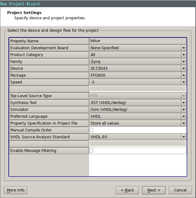
Start by following the create Project Wizard and than put the important information into the project settings that are present in the below screenshot. Note Preference related options like Preferred language and simulator can be different

Simple Xor output project
I won’t be going into the code for a simple test like this as I would assume at this point most people can produce a simple xor test if they are getting a development board like this.
use UNISIM.vcomponents.all;

entity xor_test is
        port (
                a,b, clk_p, clk_n : in std_logic;
                c : out std_logic
        );
end xor_test;

architecture Behavioral of xor_test is
        signal clk: std_logic;
begin
        IBUFDS_inst : IBUFDS
        generic map (
                DIFF_TERM => FALSE,
                IBUF_LOW_PWR => TRUE,
                IOSTANDARD => "DEFAULT")
        port map (
                O => clk,
                I => clk_p,
                IB => clk_n
        );

        process (clk)
        begin
                --- Just does the the xor output on every rising edge of the clk
                if (rising_edge(clk)) then
                        c <= a xor b;
                end if;
        end process;

end Behavioral;
The above code should synthesis just fine with out any major warnings or errors. Keep in mind the only slightly abnormal piece of code in the above example is that I used IBUFDS in order to deal with the differential clock input (see xilinx resources below for information on the IBUFDS).
Constraints for the above design
Keep mind when Xilinx developed Vivado they also change the constraints file type to be a .xdc instead of a .ucf. This does mean that the constraints in this tutorial will not be compatible with a vivado project. But the list of .xdc constraints for the zc706 will be provided in the Resource Section
Regardless, setting the constraints for the above vhdl example is quite straight forward using ise. Simply grab the .ucf file and extract the pins you want to use. In my case, I ended up using the SYS_CLK for my CLK Input (both the p and n varients), tw of the GPIO dip switches, and then one of the GPIO led outputs.
UCF example
NET  clk_p   LOC = H9 | IOSTANDARD=LVDS;
NET  clk_n   LOC = G9 | IOSTANDARD=LVDS;
NET  a     LOC = AC16 | IOSTANDARD=LVCMOS25;
NET  b     LOC = AB17 | IOSTANDARD=LVCMOS25;

NET  c     LOC = W21  | IOSTANDARD=LVCMOS25;
These two pieces of code should allow for the project to implement correctly with some minor complaints about the clock.
Programming ZC706
Note you should plug in the two usb cables for the zc706 and set the boot parametes (using the light blue dip switches) so that 4 is low and the rest are high
Firstly, I would highlighly suggest that you look at the arch wiki article on the ISE ide as some modifications are needed to get the uploading procedure to work properly. Specifically, look at the sections that detail the Xilinx Jtag, and the Digilent Jtag. Also I used the newer of the two fxload libraries (fxload-libusb) but I am not entirely sure if it makes a difference.
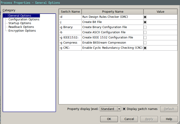
Once the pre-reqs have been taken care of, Generate the Programming file with the default parameters.

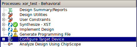
Once that has completed successfully (without severe warnings and errors), open up the ‘Configure Target Device’ Menu.

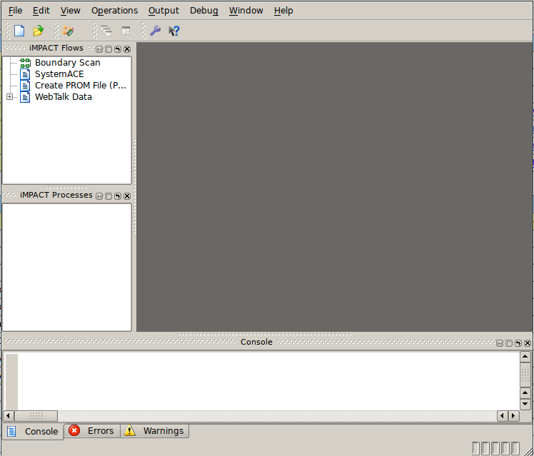
The Configure Target Device Window should open.
 In that window, you first have to do a boundary scan, that will allow you to then right click on the white portion of the window and add a Xilinx Device. A new window should pop up and you just have to specify the output programming file (should already be automatically directed to your recently created file).
Once it has succesfully loaded the file, you should be able to either right click on the ‘package’ and hit program or use the cable auto-connect button and a secondary menu should pop up verifying that the zc706 showed up. Hit okay and it should start programming the device (a light blue ‘Program Succeeded’ should pop up upon succesful completition).